Modern systems are subject to increasingly higher
constraints regarding expected behavior and services, safety, security, performance, environment,
human factors, etc. All these constraints are under the
responsibility of different stakeholders, which need to be reconciled during the solution
architectural design and development process.
Architecture as prime engineering driver
Architecture definition is a major part of engineering
activities, and notably includes analyzing operational needs,
structuring and decomposing the system, software, or hardware
assets in order to
- Provide significant information for decision-makers and
managers
- Ease the mastering of need, complexity, design and
development
- Structure engineering in a well-defined, justified,
technical frame
- Guide designers and developers to respect the product
definition drivers.
![Architecture benefits]()
Arcadia, a model-based engineering method
Arcadia is a model-based engineering method for systems,
hardware and software architectural design. It has been developed
by Thales between 2005 and 2010 through an iterative process
involving operational architects from all the Thales business
domains. Since 2018, Arcadia is registered as Z67-140 standard by AFNOR, the French national organization for standardization.
Arcadia promotes a viewpoint-driven approach (as described in
ISO/IEC 42010) and emphasizes a clear distinction between need and
solution.
![Triptique]()
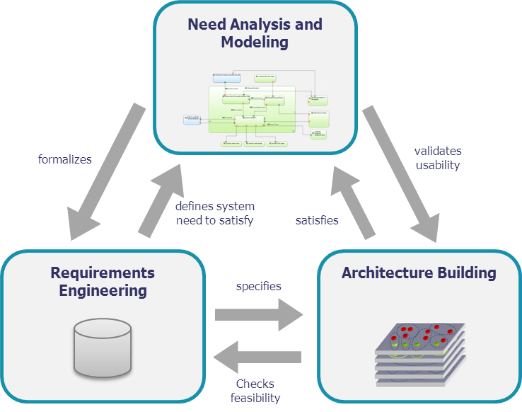
Perspectives and activities of the method have been defined in order to comply with a
few Golden Rules:
- Besides requirement engineering, drive an operational and functional/nonfunctional
need analysis, describing final user expectations, usage
conditions, and realistic integration, verification and validation conditions
- Consider engineering through three mandatory interrelated
activities, at the same level of importance:
- Need analysis and modelling
- Architecture building and validation
- Requirements engineering
- Check requirements against an architectural design
model (early architecture) for robustness and feasibility
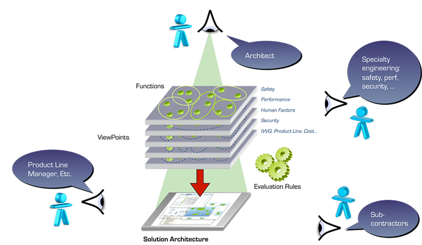
- Structure the system/hardware/software and build a logical
architecture, by searching for the best compromise between
design drivers, (non-functional) constraints and viewpoints. Each
viewpoint deals with a specific concern such as functional
consistency, interfaces, performances, real time, safety,
security, integration, reuse, cost, risk, schedule, and the ease
of adaptation (e.g. to changing requirements)
- Secure development and IVVQ through a physical
architecture which deals with technical and development issues,
favoring separation of concerns, efficient and safe component
interaction (e.g. layered architecture, generic behavior and
interaction patterns, component model, etc.)
![Phases]()
Noticeable features of Arcadia
- Models supporting enterprise-wide collaboration and
co-engineering
- An Eclipse Capella™ model is built for each Arcadia engineering
phase. All of these models are articulated through model
transformation, and related by justification links; they are
processed as a whole for impact analysis, notably in case of
required evolutions.
- Collaboration with engineering specialties is supported
by modelled engineering viewpoints to formalize constraints and
to evaluate architecture adequacy with each of them
- Collaboration with customer and subsystems engineering
relies on co-engineered models (e.g. physical architecture),
automatic initialization of need model for sub-systems, and
impact analysis means between requirements and models of
different engineering levels.
- Integration, verification, validation and qualification
(IVVQ) are driven by user capabilities, functional chains and
scenarios in the model, rather than by textual requirements
- Elaboration of product line variabilities and
configurations is optimized and assisted based on operational
market segmentation, commercial portfolio contents and
architecture constraints/adaptations to product policy, all
described in the model.
- Tailored for architectural design
- A domain-specific language (DSL) was preferred in order
to ease appropriation by all stakeholders, usually not familiar
with general-purpose, generic languages such as UML or SysML.
- Dealing with complexity and size
- Abstraction levels are in the DNA of Arcadia. Capella
advanced mechanisms have been developed to mask and confine
complexity, deal with model maintenance, large-scale modelling,
model evolution and reuse.
- Field-proven in real industrial situations
- Arcadia is currently applied in various domains and organizations, in many countries, on very large or small projects, by
thousands of users. A continuous challenging, improvement and
adaptation of both the method and its supporting workbench has
favored a very fast dissemination.
- Open to domain-specific added value
- Adapted to several lifecycles and work sharing schemes
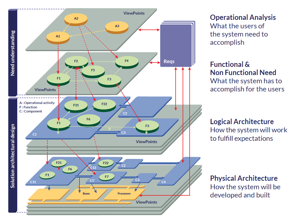
Next paragraphs give a first description of major arcadia perspectives, for a given engineering level (system, sub-system, software or hardware part…).
Definition of the Problem - Customer Operational Need
Analysis
The first perspective focuses on analyzing the customer needs and goals,
expected missions and activities, far beyond system requirements.
This analysis aims at ensuring adequate system definition
with regard to its real operational use and IVVQ conditions.
Outputs of this engineering phase mainly consist of an
“operational architecture” which describes and structures the need
in terms of actors/users, their operational capabilities and
activities (including operational use scenarios with dimensioning
parameters, and operational constraints such as safety, security,
lifecycle, etc.).
Watch the video below, illustrating this architecture level with a commented example: the level-crossing traffic control.
Formalization of system requirements - System Need Analysis
The second perspective focuses on the system itself, in order to
define how it can satisfy the former operational need, along
with its expected behavior and qualities. The following elements
are created during this step: Functions (or services) to be supported and related
exchanges, non-functional constraints (safety, security, etc.);
performance allocated to system boundary; role sharing and
interactions between system and operators; scenarios of usage, etc.
The main goal at this stage is to check the feasibility of
customer requirements (cost, schedule, technology readiness, etc.)
and if necessary, to provide means to renegotiate their content.
The functional need analysis can be completed by an initial system
architectural design model in order to examine requirements against
this architecture and evaluate their cost and consistency.
Outputs of this engineering phase mainly consist of system
functional need descriptions (functions, functional chains,
scenarios), interoperability and interaction with the users and
external systems (functions, exchanges plus non-functional
constraints), and system requirements.
Note that these two phases, which constitute the first part of
architecture building, "specify" the subsequent design, and
therefore should be approved/validated with the Customer.
Watch the video below, illustrating this architecture level with a commented example: the level-crossing traffic control.
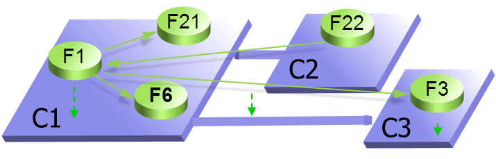
Definition of solution architecture - Logical
Architecture (Notional Solution)
This third perspective aims at building a
coarse-grained component breakdown of the system carrying
most important engineering decisions, and which is unlikely to be
challenged later in the development process. Starting from previous
functional and non-functional need analysis, a first definition of
the solution expected behavior is performed (using functions,
interfaces, data flows, behaviors…). In order to embed these
functions, one or several decompositions of the system into logical
components are to be built, each function being allocated to one
component. These logical components will later tend to be the basic
decomposition for development/sub-contracting, integration, reuse,
product and configuration management item definitions (but other
criteria will be taken into account to define the boundaries for
these items)
![Functions]()
The building process has to take into account architectural
drivers and priorities, viewpoints and associated design rules,
etc. For the component breakdown to be stable in further engineering
phases, all major (non-functional) constraints (safety, security,
performance, IVV, cost, non-technical, Etc.) are taken into account
and compared to each other so as to find the best trade-off. This
method is described as "viewpoint-driven", where viewpoints
formalize the way these constraints impact the system architecture.
Outputs of this engineering phase consist of the selected
logical architecture which is described by a functional
description, components and justified interfaces definition,
scenarios, modes and states, along with the formalization of all
viewpoints and the way they are taken into account in the
components design.
Since the architecture has to be validated against the need
analysis, links with requirements and operational scenarios are
also to be produced.
![Viewpoints]()
Watch the video below, illustrating this architecture level with a commented example: the level-crossing traffic control.
Definition of solution architecture - Physical Architecture
The fourth perspective has the same intent as the logical architecture
building, except that it defines the “final” architecture of the
system at this level of engineering. Once this is done the model is
considered ready to develop (by "lower" engineering levels).
Therefore, it introduces further details and design decisions,
rationalization, architectural patterns, new technical services and
behavioral components, and makes the logical architecture vision
evolve according to implementation, technical and technological
constraints and choices. It notably introduces resource components
that will embed former behavioral components. The same
viewpoint-driven approach as for logical architecture building is
used.
Outputs of this engineering phase consist of the selected
physical architecture which includes components to be produced,
formalization of all viewpoints and the way they are taken into
account in the components design. Links with requirements and
operational scenarios are also produced.
Watch the video below, illustrating this architecture level with a commented example: the level-crossing traffic control.
Building Strategy - Contracts for
Development and IVVQ
The fifth and last perspective is a contribution to an EPBS
(End-Product Breakdown Structure), and models describing
specification of each sub-system, hardware or software component;
it takes benefits from the former architectural work, to formalize
the component requirements definition and prepare a secured IVVQ.
All previous hypotheses and imposed constraints associated to
the system architecture and components are summarized and checked
here.
Outputs from this engineering phase are mainly new models describing component
integration contracts, collecting all necessary expected properties
for each component to be developed.
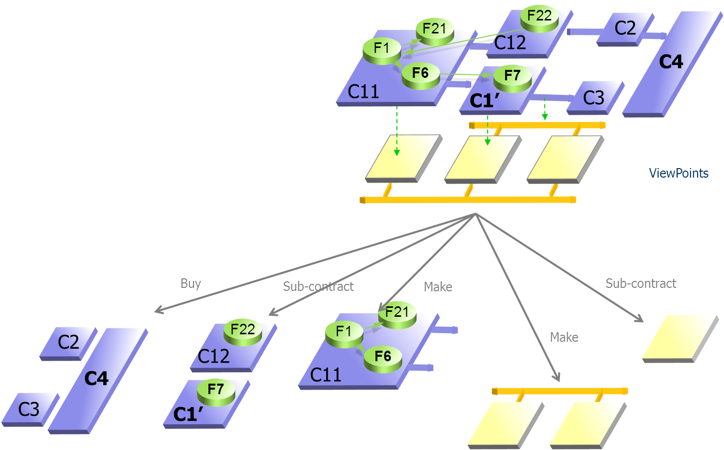
Co-Engineering, Sub-Contracting and Multi-Level Engineering
The physical architecture is the preferred place for co-engineering
between systems, software, and hardware stakeholders.
![Coengineering]()
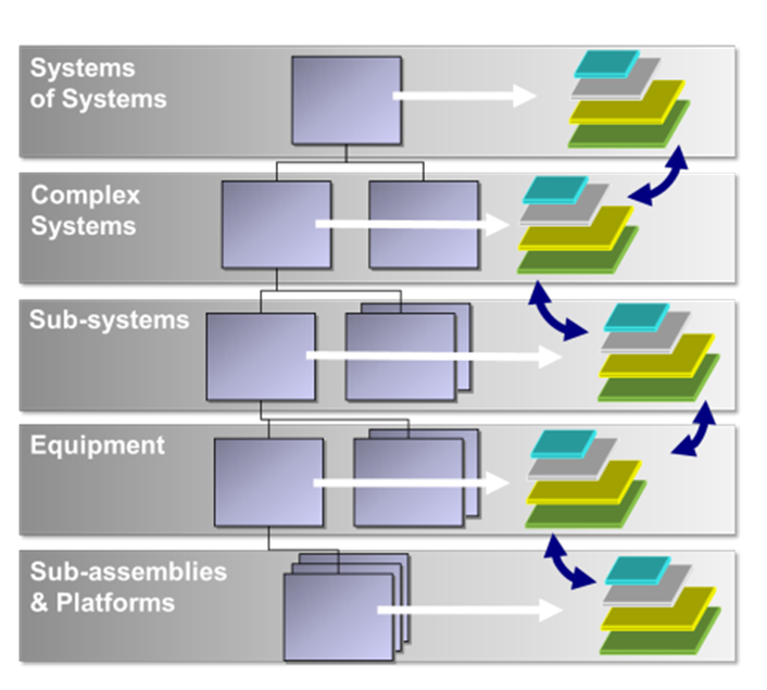
Arcadia can be applied in a recursive way at each level of
system breakdown, so that a subsystem of the current system of
interest becomes the system at the next level of interest, until
single discipline subsystems or procurement items or COTS are
identified.
The physical architecture at a given level of interest
defines the components to be developed at the level above,
according to the corresponding component integration contract.
Level "n" need analysis is restricted to each component scope and
neighborhood, in order to define its IVVQ context while preserving
Intellectual Property constraints.
![Multi-level]()
Adaptation of Arcadia to Dedicated Domains, Contexts, Etc.
Beyond the transverse, common architectural design work, each
organization, in the field of its own business, constraints and
know-how, should tailor the method steps by adapting them to
their own domains, products and programs. This includes:
- Definition of a reference architecture (including
architecture drivers) for each key product and software element
- Definition of appropriate viewpoints adapted to the
domain, product and architecture
- Definition of complementary dedicated engineering rules
- Selection of relevant architectural patterns for the
domain, product, and technologies considered
- Setting up of models, based on the reference architecture
and viewpoints, and basis for simulation, early validation,
automation of the design process (key for productivity gains)
- Definition of adjustment rules for each of its contexts
- Dissemination in the engineering teams (training,
coaching)...
Adaptation to different Lifecycles
The recommended method described in this document takes best
benefit from a top-down approach:
- Starting from operational and system need to define and validate
requirements
- Building a "technology neutral" logical architecture
dealing with non-functional constraints
- Then specifying technical functions and services of a
physical architecture to implement it in the best way
Yet many constraints which need to be taken into account
arise from the industrial context:
- Technical or technological limits
- Available technology, COTS
- Existing legacy to be reused
- Product policy imposing the use of given hardware boards,
software components...
- Industrial constraints such as available skills, the
necessity to sub-contract, and export control...
This is the reason why Arcadia can be applied according to several
lifecycles and work sharing schemes. Great care has been taken in
the method, the language and the Capella workbench to not impose one
single engineering path (e.g. top-down) but to be adaptable to many
lifecycles: Incremental, iterative, top-down, bottom-up,
middle-out, Etc.. The method is inherently iterative.
Examples of iterations or non-linear courses are:
- Need analysis starting from requirements, due to a lack of
operational knowledge (a kind of reverse engineering of
operational need)
- Requirements analysis anticipating logical or even
physical architecture, to check for feasibility by
defining/confronting to an early architecture
- Logical architecture anticipating (part of) physical
architecture, e.g. to check for performance issues
- Physical architecture adapting to subcontracting
constraints, or built from assembling reusable, existing
components
- Components contract definition iterating on physical
architecture to secure integration and refine contract parameters